SV-450
Door Configuration |
Internal Dimensions |
External Dimensions |
Volume |
Capacity |
|
|---|---|---|---|---|---|
SV-450 |
Vertical |
25.6” x 27.6” x 39” |
51.2” x 75.6” x 50” |
450 |
15.9 |
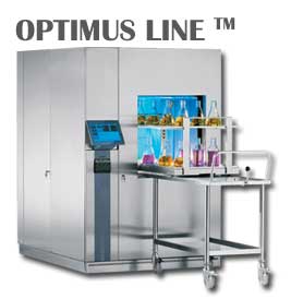
Request A Quote For An Optimus
The Sterilco Steam Sterilizers are designed for applications in laboratories for sterilization of materials such as instruments, textiles, rubber goods, liquids, agars, animal diet, cages etc.
TECHNICAL SPECIFICATION
MOUNTINGS
QUALIFICATION
IMHS Industrial Moist Heat Sterilization: International Standard 11134:1994
ASME American Society of Mechanical Engineers
UL Underwriters Laboratory
CETL Canadian Testing Laboratories (for conformance to CSA)
NFPA National Fire Prevention Association
OSHA Occupational Safety and Health Administration
NPC National Plumbing Code
NEC National Electrical Code
NEMA National Electrical Manufacturers Association
EN285 British Standard for Sterilization
CHAMBER
The chamber is mechanically polished to a 50 Ra. As option, the chamber can be polished to a 25 Ra or a mirror finish with a Ra of 10u inch or better. This feature greatly enhances the sanitary aspects of the chamber, as well as the clean ability, which translates into longer lasting more aesthetically pleasing sterilizers.
JACKET
DOORS:
Vertical Sliding Door
The door is sealed by air pressurizing the continuous O-ring gasket, which is recessed within the chamber head ring against the door. The gasket is retracted by vacuum before the door is opened.
INSULATION
FRAME
FRONT PANELING
PIPING
VALVES
OVERPRESSURE RELIEF
VALIDATION AND LOAD PORTS
VACUUM PUMP
EXHAUST COOLING SYSTEM
CONTROL SYSTEM
Double-Microprocessor Control System
-
Advanced 8” touch screen allows cycle programming and indicates the sterilizer operating state. Alarms are announced audibly and indicated in clear text. The operator interface is mounted on the front fascia, on the loading side of the sterilizer. -
Fourteen (14) programmable cycles are available with a wide range of programmable parameters, which provides for a high degree of functionality and allows great freedom in designing cycles for various loads. -
Cycle parameters and calibration are protected from unauthorized access with pass codes. -
Dual RTD’s provides the precise control, evaluation and regulation of temperature inside the chamber. -
Absolute dual pressure sensors are equipped for the precise control of pressure in the chamber and jacket and vacuum in the chamber. -
Indication of chamber temperature and pressure in digital graphical display are indicated on the operator interface and printed. -
Complete automatic diagnostic system displayed on the operator interface and printed on the printout. -
To allow a safe entry into the chamber, the door control system can be locked out for personnel safety.
Printer
The printer provides a digital printout of cycle progression and information including any fault statementsduring the entire cycle. The following process parameters are recorded on the 4.5” wide paper for easy reading. The following events are documented during the cycle:
-
Date -
Sterilizer Identification -
Load Identification -
Cycle Parameters -
Cycle Steps -
Chamber Temperature -
Exposure Start Time -
Exposure End Time -
Alarms if Any (Real Time) -
Graphic printout of the complete cycle -
Fault diagnosis print during any alarm (shows valve positions for easy diagnosis)
Chip Card System
PREPROGRAMMED CYCLE DESCRIPTIONS
Dry Goods ¾ Vacuum Cycle (Standard)
This cycle provides effective sterilization of hard goods, filters, linens, and other porous materials, wrapped goods, and product that is unaffected by vacuum. This cycle is also highly effective at removing moisture from the load during drying. At the end of the cycle, air pulses can be initiated to aid in drying.-
Program P1 – Exposure Temperature 134° C for 4 minutes with short drying
For instruments, single wrapping or unwrapped, pre-vacuum method with short drying phase -
Program P2 – Exposure Temperature 134° C for 7 minutes with 10 minute drying for textiles, instruments, wrapped goods, pulsing vacuum method with drying phase -
Program P3 – Exposure Temperature 134° C for 7 minutes with 20 minute drying
For heavy instruments, wrapped goods, pulsing vacuum method with super-drying-program -
Program P4 – Exposure Temperature 121° C for 20 minutes with 20 minute drying For glassware, heat resistant items of synthetic material or rubber, pulsing vacuum method with drying phase
Solution Cycle ¾ Gravity Air Removal / Ramped Exhaust
This cycle effectively sterilizes liquid products or items in vented or sealed glass containers. Exhaust ramping gradually returns liquids to a temperature below boiling. A movable RTD is equipped inside the chamber for placement into the product. The RTD ensures that the liquid is below the boiling point before the chamber door is allowed to open.-
Program P5 – Exposure Temperature 121° C for 20 minutes with ramped exhaust
For vented solutions in glass or heat resistant containers
Test Cycles
- Program P6 – Vacuum Leak Test – Verification of chamber piping and door seal integrity.
The acceptable maximum leak rate is 1 mm HG/min. over a 10 minute period following a fixed stabilization time. -
Program P7– Dart Test – For verification of effective removal of residual air in the chamber and load during testing.
Test cycle determines if even and rapid steam penetration into the test load has occurred. Cycle parameters are preprogrammed and fixed.